

Are air flow sensors important for car engines? Why.
Air flow sensor, also known as air flow meter, is one of the important sensors of efI engine. It will be inhaled air flow into electrical signals sent to the electronic control unit (ECU), as one of the basic signals to determine the fuel injection, is the suction engine air flow sensor.
Description Of Air Flow Sensor
In order to obtain the optimal concentration of the mixture in the electronic control gasoline injection engine under various operating conditions, the amount of air inhaled into the engine at each moment must be measured correctly, which is the main basis for ECU to calculate (control) the fuel injection amount. If the air flow sensor or circuit failure, the ECU can not get the correct intake signal, can not normally control the amount of fuel injection, will cause the mixture is too thick or too thin, so that the engine does not run properly. There are many types of air flow sensors in electronic control gasoline injection system. Common air flow sensors can be divided into blade (wing) type, core type, hot wire type, hot film type, Karman vortex type and so on according to their structure.
The Structure Principle Of Air Flow Sensor
In electronic controlled fuel injection device, the air flow sensor, which measures the amount of air absorbed by the engine, is one of the important components to determine the control accuracy of the system. When the control precision of air/fuel ratio (A/F) is ±1.0, the allowable error of the system is ±6[%]~7[%]. When the allowable error is distributed to each component of the system, the allowable error of the air flow sensor is ±2[%]~3[%].
The ratio of Max /min of the maximum and minimum air flow in the gasoline engine is 40~50 in the natural intake system and 60~70 in the system with supercharging. Within this range, the air flow sensor should be able to maintain the measurement accuracy of ±2~3[%]. Air flow sensors used in electronically controlled fuel injection devices should not only maintain measurement accuracy over a wide measurement range, but also have excellent measurement responsiveness. Pulsating air flow can be measured, and the processing of output signals should be simple.
According to the characteristics of air flow sensor, the fuel control system is divided into L type control which directly measures the intake air and D type control which indirectly measures the intake air (indirectly measures the intake air according to the negative pressure of intake manifold and the engine speed). Type D control microcomputer in ROM, stored in advance with engine speed and the pressure inside the intake pipe parameters under the various states of air inflow, the microcomputer based on measured under different running condition of inlet pressure and rotational speed, by reference to ROM memory into the air, can calculate the amount of fuel L type air flow meter used in the control and general industrial flow sensor basic same, However, it can adapt to the harsh environment of the car, but it can respond to the requirements of the rapid change of the flow when stepping the accelerator and can detect the uneven airflow caused by the shape of the intake manifold before and after the sensor with high precision.
The original electronic fuel injection control system did not use a microcomputer. At that time, valve type air flow sensors were used, but as microcomputers were used to control fuel injection, several other air flow sensors also appeared.
The structure of valve type air flow sensor.
Valve type air flow sensor is installed on the gasoline engine, installed between the air filter and throttle, its function is to detect the engine intake gas, and the detection results into electrical signals, and then input into the computer. The sensor is composed of air flow meter and potentiometer.
First look at the working process of the air flow sensor. The air inhaled by the air filter rushes to the valve, and the valve turns to the position where the air intake and the return spring balance and stops. That is to say, the valve opening is proportional to the air intake. In the rotating shaft of the valve is also equipped with a potentiometer, the sliding arm of the potentiometer rotates synchronously with the valve, and the voltage drop of the sliding resistance is used to convert the opening of the measuring piece into electrical signals, and then input to the control circuit.
Kaman vortex air flow sensor
In order to overcome the shortcomings of valve air flow sensor, that is, on the premise of ensuring the accuracy of measurement, expand the measuring range, and cancel the sliding contact, a small and lightweight air flow sensor, that is, kaman vortex air flow sensor was developed. Kaman vortex is a physical phenomenon. The detection method and electronic control circuit of vortex have nothing to do with the detection accuracy. The detection accuracy is determined by the path area of air and the size change of the vortex column. And because the output of this sensor is an electronic signal (frequency), so the input signal to the control circuit of the system, the AD converter can be omitted. Therefore, in essence, Kaman vortex air flow sensor is a signal suitable for microcomputer processing. This sensor has the following three advantages: high testing accuracy, can output linear signal, signal processing is simple; Long-term use, the performance will not change; Temperature and atmospheric pressure do not need to be corrected because it is measuring volume flow.
When there is a Kaman vortex, with the change of speed and pressure, the basic principle of flow detection is to use the change of speed. The signal is square wave and digital signal. The more air intake, the higher the frequency of the Kaman vortex, the higher the frequency of the air flow sensor output signal.
Temperature and pressure compensation air flow sensor, mainly used in industrial pipeline fluid flow measurement medium, such as gas, liquid, steam and other media. It is characterized by small pressure loss, large measuring range and high precision. It is almost not affected by fluid density, pressure, temperature, viscosity and other parameters when measuring volume flow under working conditions. No moving mechanical parts, so high reliability, small maintenance. Instrument parameters can be stable for a long time. The instrument uses piezoelectric stress sensor, high reliability, can work in the working temperature range of -10℃ ~ +300℃. Analog standard signal, digital pulse signal output, easy to use with computers and other digital systems, is a relatively advanced, ideal flow.
The biggest advantage of air flow sensor is that the instrument coefficient is not affected by the physical properties of the measuring medium, and can be extended from a typical medium to other media. However, the frequency range of liquid and gas varies greatly due to the wide range of flow velocity. In the amplifier circuit dealing with vortex street signal, the circuit parameters are different because the pass band of the filter is different. Therefore, the same circuit parameters cannot be used to measure different mediums.
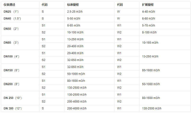
Measuring Range Of Air Flow Sensor
The instrument passage of the air flow sensor and its measuring range are shown in the following table:
Detection Principle Of Air Flow Sensor
Overhead electric wires in the field whine when blown by the wind. The higher the wind speed, the higher the sound frequency, this is because the air flow through the wire vortex caused by the formation of liquid, gas and other fluids will occur in this phenomenon, the use of this phenomenon can be made into vortex flow sensor. The flow rate can be measured based on the frequency of two vortices created by placing columns in the pipe. Because vortex into two parallel lines, and alternating left and right, similar to street lights on both sides of the street, so it is called vortex street. Because this kind of phenomenon to become first found, so also called karman vortex street ultrasonic type karman vortex air flow sensor ultrasonic air flow sensor is equipped with two inlet channel, main and side channel, inlet flow detection part is located in the main, set up side channel purpose is in order to be able to adjust the flow rate of the main So that the detection characteristics of the main channel is ideal. In other words, for engines with different exhaust volume, by changing the size of the air flow sensor channel section, one specification of air flow sensor can be used to cover a variety of engines. Karman vortex generator is composed of a triangular column and a number of vortex amplifiers on the main channel. Produced in the sides of the karman vortex in relatively set belongs to the electronic detection device of ultrasonic transmitter and ultrasonic receiver, also can put the two parts as sensors, electrical signal produced by the two electrons by the air flow sensor control circuit (hybrid) plastic, enlarged as the ideal waveform, then input to the computer. In order to use ultrasonic inspection vortex, the inner wall of vortex channel is stuck with sound-absorbing material, the purpose is to prevent irregular reflection of ultrasonic wave.
Karman Vortex Air Flow Sensor For Pressure Change Detection
Alternation happened on both ends of the eddy current from the vortex generator, thus produced by alternately on both ends of the vortex generator, so vortex generator at both ends of the pressure is also changes, the change of the pressure on the conical vortex generator downstream side column guide hole lead to the mirror cavity, mirror in the cavity mirror is made of very fine tensioning belt tension, so, In addition, the plate spring is used to add appropriate tension to the tension belt, so that the pressure changes in addition to vibration and vortex pressure are difficult to cause influence, so that stable torsion and vibration can be obtained.
The pressure formed by the emergence of vortex passes through the pressure guide hole to the reflector cavity, and synchronizes with the pressure change in the reflector cavity. The reflector forms torsion and vibration in the tension zone. The mirrors are very lightweight and operate even at low flow rates with very little pressure change. In the upper part of the reflector, the corresponding light sensor composed of light-emitting diode and photosensitive triode is configured. When the light emitted by the diode is reflected by the reflector and hit the photosensitive triode, it will become current and output after passing through the waveform circuit.
Air Flow Sensor Characteristics
When the throttle valve is made from closed to fully open within 30 seconds, that is, fast open, the curve is the output characteristics of the Karman vortex air flow sensor after F/V transformation, and the curve is the throttle opening characteristics. The air flow sensor can accurately reflect the relationship between air velocity and frequency (1~45 ms) : There is a linear relationship between air velocity and vortex frequency over a very wide range of velocity.
Ultrasonic Karman vortex air flow sensor with differential pressure sensor:
Karman vortex air flow sensor features: high precision, long life, high reliability. However, high-performance engines that further reduce fuel consumption, increase the output power of the engine also extended into gas detection scope, but the old type ultrasonic karman vortex air flow sensor in high traffic areas will produce the phenomenon of over modulation, influenced by the factors, this kind of sensor has the defects of lack of measuring range. Therefore, the air flow sensor with differential pressure sensor is developed.
1. the use of small pressure loss vortex generator: the function of vortex generator is to form a stable vortex in the whole flow range.
2. Pipe structure with small pressure loss.
3. Measure the tiny vortex pressure.
4. air flow sensor with differential pressure sensor.
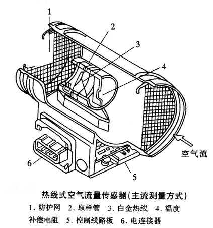
Structure Of Hot Wire Air Flow Sensor:
As a heating element, the hot wire is made of 70um diameter platinum wire, tensioned inside the pipe, designed to be 120 degrees higher than the intake temperature. The temperature sensor also has an air temperature compensation resistor. It is formed from a platinum film printed on an alumina ceramic substrate and is mounted in a tube with a precision resistor. In order to prevent the dust attached to the hot wire caused by performance decline, dust combustion circuit, when the ignition switch is placed in the open gear, under certain conditions, the hot wire will be heated to more than 1000 degrees, and keep about 1 second, burn dust and other attachments. Because platinum wire is used as heating element, so the response is good.
Similarly, there are hot film wire air flow sensors (H/F). Similar to H/W sensors, H/F also uses flat film resistors as heating elements. The manufacturing method is: the thin film of platinum evaporates on the alumina substrate, forms a comb resistance through graphic production, and then adjusts to the required resistance value. After that, the protective film is made, and then the electrode leads are connected. Compared with hot wire type, hot film type heating element is slightly less responsive, but because it is made by graphical method, so the resistance value is higher, the consumption of current is small, can be small and lightweight. In addition, because its heating element is planar, when viewed from upstream, it can be managed to make its projection area small, so that when set in the metering channel can reduce the attachment, that is, improve the stain resistance.
Throttle
The throttle sensor is used to convert the throttle opening into a voltage signal to control the fuel injection volume through the ECU. There are two commonly used switch throttle position sensor and linear throttle sensor, of which the switch throttle position sensor although the structure is relatively simple, but its output is discontinuous. In addition to the above three, for automotive engine electronic control of the sensor and pressure sensor, oxygen sensor, temperature sensor, knock sensor, crankshaft position sensor, speed sensor and so on. All electronic control systems or devices in modern cars are inseparable from sensors, such as automatic transmission, automotive brake anti-lock system, drive anti-skid system, etc. Especially in recent years, there are more and more electronic devices used in vehicles, such as safety alarm devices, communication devices, entertainment devices and auxiliary driving devices for improving comfort and reducing fatigue. Of course, domestic automotive electronic control technology has just started, mainly focused on the electronic control of the engine, because of this, automotive sensor pressure switch will have a broader space for development in China.
The Air Flow
Air flow sensor is a very important control content in the electronic control system of the engine, which is the optimal air combustion control. In order to achieve this goal, the intake air flow of the engine must be accurately measured. Commonly used air flow sensors are throttle air flow meter, Karman vortex air flow meter, hot wire air flow meter, hot film air flow meter. Air valve type air flowmeter has the advantages of simple structure and high reliability, but large intake resistance, slow response and large volume; The hot-wire air flowmeter has no moving parts, so it not only works reliably, but also responds quickly. Its disadvantage is that the error is large when the velocity distribution is uneven. Although the working principle of thermal film type air flow meter and the hot line type air flow meter are similar, but because of the hot film type sensors do not use the platinum wire as hotline, but hot line resistance, compensation resistance made of thick film technology, such as in the same ceramic substrate, the heating element is not directly bear force generated by air flow, thereby increasing the strength of heating element, Not only the reliability of the air flowmeter is further improved, but also the error is reduced and the performance of the weighing sensor is better
Air Flow Amount Of Fuel Injection
The air flow sensor (MAF) calculates the amount of air entering the engine by sensing the heat taken away by the air entering the engine. The power system control module (PCM) uses the air quality flow to monitor the actual amount of air entering the engine, and calculates the main fuel supply. When the amount of air entering the engine is large, the value perceived by the air flow sensor is large, indicating that the engine is in the acceleration or high load condition, and vice versa, indicating that the engine is in the deceleration or idle state.
Long/short term fuel adjustment is achieved by changing the nozzle pulse width by PCM to keep the engine's air-fuel ratio as close to 14.7∶1 as possible (the optimal ratio). Both short-term and long-term fuel adjustment data can be checked by the vehicle diagnostic instrument. The important difference between short-term and long-term fuel adjustments is that the former represents a small change over a short period of time while the latter represents a large change over a long period of time.
Short-term fuel adjustment is part of the electric control system of the automobile engine. When the engine is closed loop, short-term fuel adjustment makes small, temporary modifications to the air-fuel ratio. The short-term fuel adjustment continuously monitors the output voltage from the oxygen sensor with 0.45V as a reference point. When the engine is closed loop, the signal voltage of the oxygen sensor should vary within a constant range of 0.1 ~ 0.9V. When the oxygen sensor voltage monitored by the PCM changes steadily around the reference point 0.45V, the PCM continuously adjusts the fuel supply to ensure that the air-fuel ratio of the engine is as close to 14.7:1 as possible. Short-term fuel adjustment values are expressed as a percentage between -100% and +100%, with the midpoint being 0%. If the short-term fuel adjustment value is 0%, then the air fuel ratio is ideal at 14.7∶1 and the mixture is neither too thick nor too thin. If the short-term fuel adjustment shows a positive value above 0%, the mixture is thin and the PCM is adjusting the fuel supply system to increase the amount of fuel injected. If the short-term fuel adjustment shows a negative value of less than 0%, the mixture is thicker and PCM is adjusting the fuel supply system to reduce the amount of fuel injected. If the mixture is too thin or too thick beyond the range of short-term fuel adjustment, a long-term fuel adjustment is required.
The long-term fuel adjustment value is derived from the short-term fuel adjustment value and represents the long-term correction of the fuel deviation. If the long-term fuel adjustment shows 0%, it indicates that fuel supply is appropriate in order to maintain the air-fuel ratio controlled by PCM. If the long-term fuel adjustment shows a negative value of less than 0%, it indicates that the mixture is too thick and the injection volume is decreasing (the injection pulse width is small); If the long-term fuel adjustment shows a positive value above 0%, it indicates that the mixture is too thin and the PCM is compensating by increasing the fuel supply (increasing the injection pulse width). The value of the long-term fuel adjustment can indicate how much the power control module has compensated. Although short-term fuel adjustments allow for a wider range of small adjustments to fuel supply more frequently, long-term fuel adjustments can indicate a tendency for short-term fuel adjustments to lean or thicken. Long-term fuel adjustment can significantly change fuel supply in the desired direction over a longer period of time.
We will do a good job in every content,do our best to solve the problem for each customer,Thank you for your reading.


Leave A Comment