

Common faults of automobile sensors and their detection methods?(1)
Each car has more than 100 sensors, mainly used for control (engine electronic control system) and measurement (instrument and indicator light display system), is a super popular repair project in the garage, a technician can master this skill is particularly critical.
The identification, fault performance, detection method and practical rhyme of eight common sensors (intake temperature sensor, air flow sensor, intake pressure sensor, throttle position sensor, crankshaft position sensor, camshaft position sensor, heating oxygen sensor, detonation sensor) are summarized.
 Intake Temperature Sensor
 Intake Temperature Sensor Identification
The intake temperature sensor is generally installed in the air flow meter or the intake manifold behind the air grid. A sensor used to measure the temperature of air intake to an engine.
 Failure Performance Of Intake Temperature Sensor
But a failure, the engine mixture is too thick or too thin, directly lead to cold start difficult, and idle instability after starting.
Intake Air Temperature Sensor Detection Method
Because its structure is basically similar to water temperature sensor, the detection method of water temperature sensor can be used during inspection. Under normal conditions, the resistance is about 2-3KΩ at 20 ° C and 0.4-0.7KΩ at 60 ° C. If the test results do not meet the value range, replace the sensor. When the air inlet temperature sensor installed in the air flow meter is damaged, the air flow meter should be replaced.
The Intake Temperature Sensor Is Practical

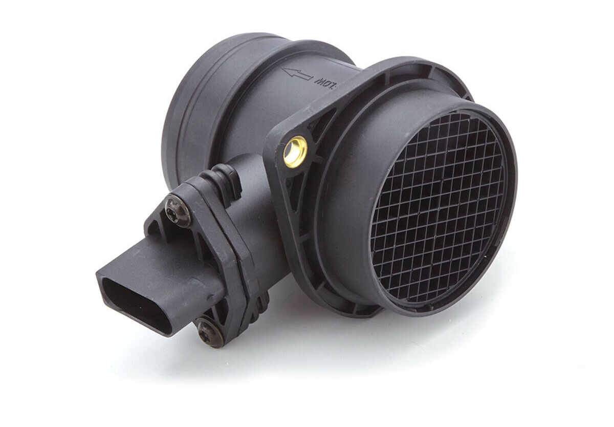
 Air Flow Sensor
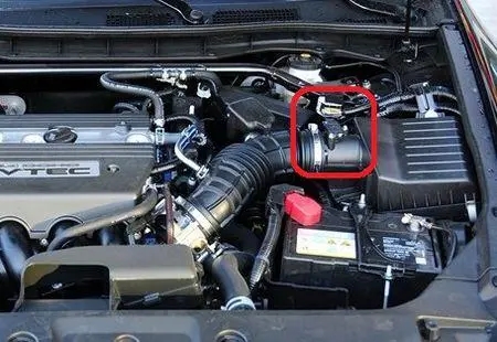
Air Flow Sensor Installation Position
Air Flow Sensor Is Also Called Air Flow Meter (Afm), Generally Installed In The Air Filter And Throttle Body. Used To Measure The Amount Of Air Taken In By The Engine.
Air Flow Sensor Failure
The engine won't rev up once it breaks down.
Air Flow Sensor Detection Method
Method One:
When the engine is running, pull out the plug of the air flow sensor. If the fault persists, the sensor is damaged. If the fault disappears, the sensor is not damaged. If the fault is reduced, it indicates that the sensor signal is inaccurate.
Method Two:
The dynamic signal voltage is measured at the signal end of the plug. Under idle condition, the standard voltage is 0.8-1.4V; When accelerated to full load, the voltage signal can approach 4V. If not, the air flow sensor itself may be damaged.
Method Three:
Since the air flow sensor signal is the main basis for controlling the air-fuel ratio, infrared tail gas analyzer can be used to measure the tail gas composition of the engine at idle speed and at the stable condition of 2000r/min. If the difference from the standard value is too large, it may be the fault caused by poor performance of the air flow sensor.
Practical Rhymes
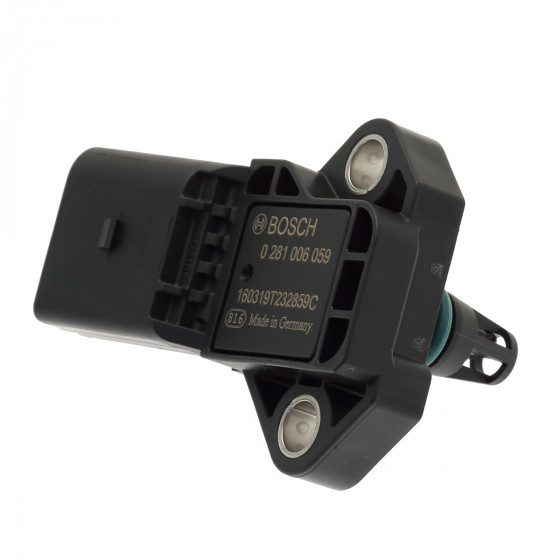
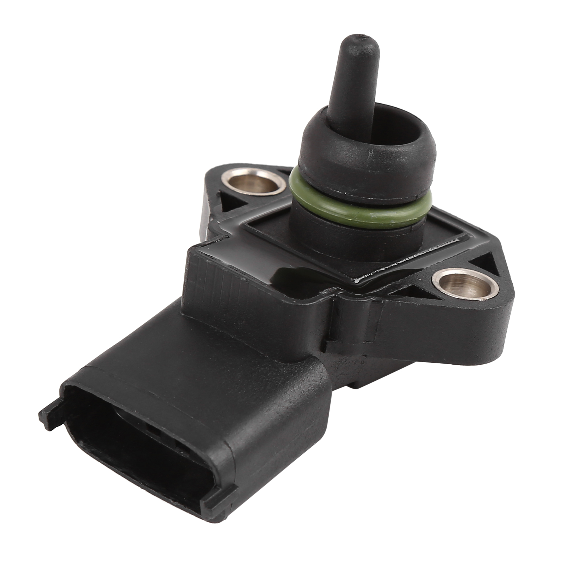
 Intake Pressure Sensor
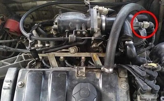
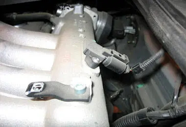
Installation Position Of Inlet Pressure Sensor
The intake pressure sensor is generally installed beside the throttle door. Used to control the size of the engine fuel injection.
Failure Performance Of Intake Pressure Sensor
But a fault will cause ignition difficulties, idle instability, weak acceleration and other problems.
Intake Pressure Sensor Detection Method
Method One:
Check the power supply voltage. Remove the pressure sensor wire harness plug ON the intake manifold, put the ignition switch in the ON position, and then use the multimeter voltage file to measure the voltage between the power terminals ON the wire harness plug, its value should conform to the value of the vehicle to be repaired, otherwise it should replace or repair the electric control wire harness;
Method Two:
Check the output voltage. Remove the sensor and the intake manifold vacuum hose connected, the sensor directly and atmosphere are interlinked, then put the ignition switch ON, measured with voltmeter in wiring harness plug place electronic control unit (ECU) sensor output voltage, and then to add vacuum sensor, can measure the output voltage under different vacuum, the voltage should be increased as the density of the vacuum is reduced, or a sensor should be replaced Device.
Practical Rhymes
 Throttle Position Sensor
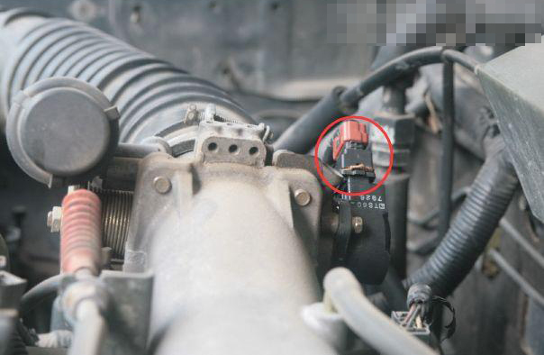
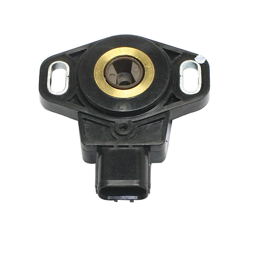
Throttle Position Sensor Position
The throttle position sensor is generally installed on the throttle body. Used to control the fuel injection time of the engine.
Throttle Position Sensor Failure Performance
But a fault will lead to engine idle operation is not normal, engine jitter and sluggish acceleration response.
Throttle Position Sensor Detection Method
Throttle position sensors are mainly divided into switching output and linear variable resistance output.
Switching Output Type:
Check the conductivity between the terminals, the ignition switch is placed in the OFF position, unplug the throttle position sensor connector, insert a thickness gauge of appropriate thickness between the throttle limit screw and the limit rod; Use multimeter Ω range on throttle position sensor connector to measure the conductance of idle contact and full load contact. When the throttle is fully closed, idle contact IDL should turn on; When the throttle is fully open or nearly fully open, the full load contact PSW should be turned on; In other degrees of openness, both contacts should not conduct, otherwise, should be adjusted or replaced.
Linear Variable Resistor Output Type:
Check the idle contact conductance, put the ignition switch in the OFF position, unplug the throttle position sensor wire connector, and measure the IDL conductance of idle contact on the throttle position sensor connector using the multimeter ω range. When the throttle is fully closed, idL-E2 terminals should be on (resistance is 0); when the throttle is open,IDL-E2 terminals should not on (resistance is ∞), otherwise it should be replaced.
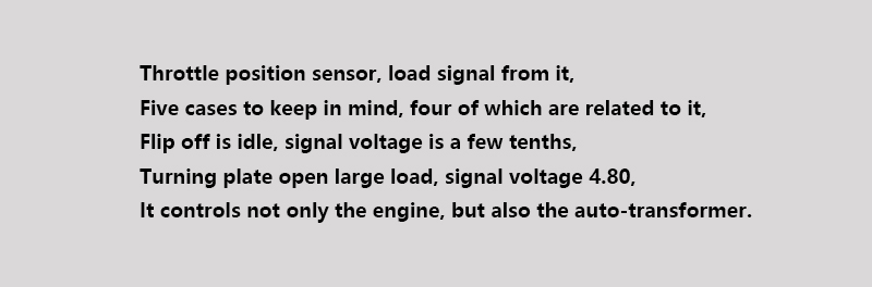
Practical Rhymes
 Crankshaft Position Sensor
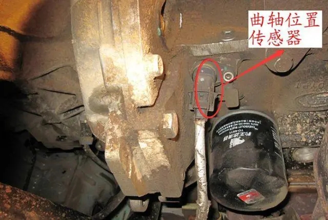
Crankshaft Position Sensor Position
The crankshaft position sensor is generally installed on the rear of the crankshaft pulley. Used for the determination of engine speed.
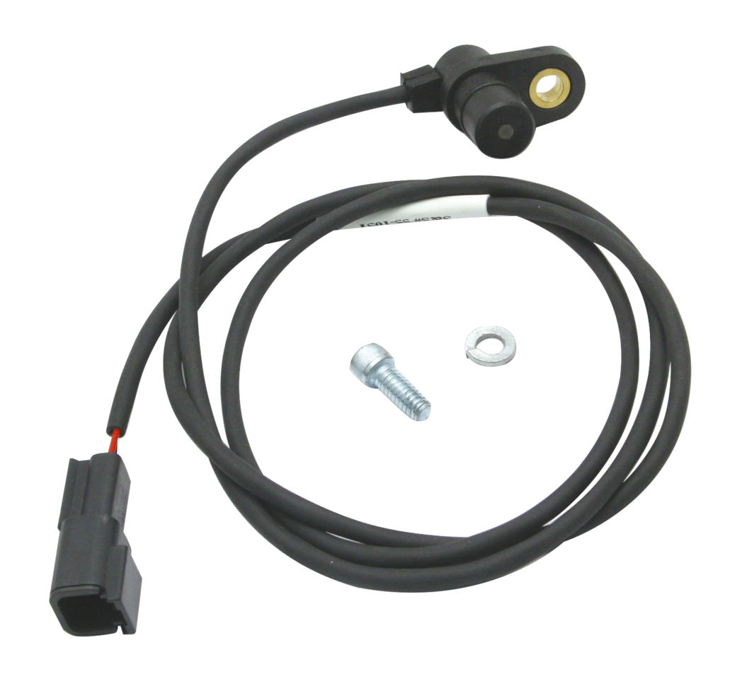
Crankshaft Position Sensor Fault Performance
Once the fault, the car has no high voltage, no ignition, no fuel injection, can not hit the car.
Crankshaft Position Sensor Detection Method
Both the magnetoelectric and Hall crankshaft position sensors need to check the clearance between the sensor and the target wheel.
Magnetoelectric: resistance meter can be used to detect its resistance, resistance value is generally between several hundred to more than one thousand ohms, depending on the model; It can also start the engine to measure its voltage, which should increase with the increase of engine speed.
Hall Type: can first test whether there is a supply voltage, the measurement needs to open the switch, and then measure the sensor grounding, and finally measure the signal, the signal voltage should be close to the reference voltage and 0V. Hall type crankshaft position sensor has three lines, one is the power line (to provide reference voltage), one is the ground line, one is the signal line. When the sensor works, the signal line will send a square wave signal, the amplitude of the square wave is close to the reference voltage, the bottom of the square wave is close to 0V, the higher the engine speed square wave frequency will be greater.
Practical Rhymes
We will do a good job in every content,do our best to solve the problem for each customer,Thank you for your reading.


Leave A Comment